 EN
EN
 AR
AR
 HR
HR
 DA
DA
 NL
NL
 FR
FR
 DE
DE
 EL
EL
 HI
HI
 IT
IT
 JA
JA
 KO
KO
 NO
NO
 PL
PL
 PT
PT
 RO
RO
 RU
RU
 ES
ES
 TL
TL
 IW
IW
 ID
ID
 SR
SR
 SK
SK
 UK
UK
 VI
VI
 TH
TH
 TR
TR
 AF
AF
 MS
MS
 IS
IS
 HY
HY
 AZ
AZ
 KA
KA
 BN
BN
 LA
LA
 MR
MR
 MY
MY
 KK
KK
 UZ
UZ
 KY
KY
In the demanding world of power transmission and precision conveying, even subtle design modifications can lead to substantial performance gains. One such crucial, yet often overlooked, feature is the PU timing belt back groove, also commonly referred to in the industry as a reverse groove, anti-bending groove, or ventilation groove.
This article provides an in-depth exploration of what these longitudinal grooves are, how they are manufactured, and, most importantly, the practical operational benefits they deliver to industrial machinery.
1. Defining the PU Timing Belt Back Groove
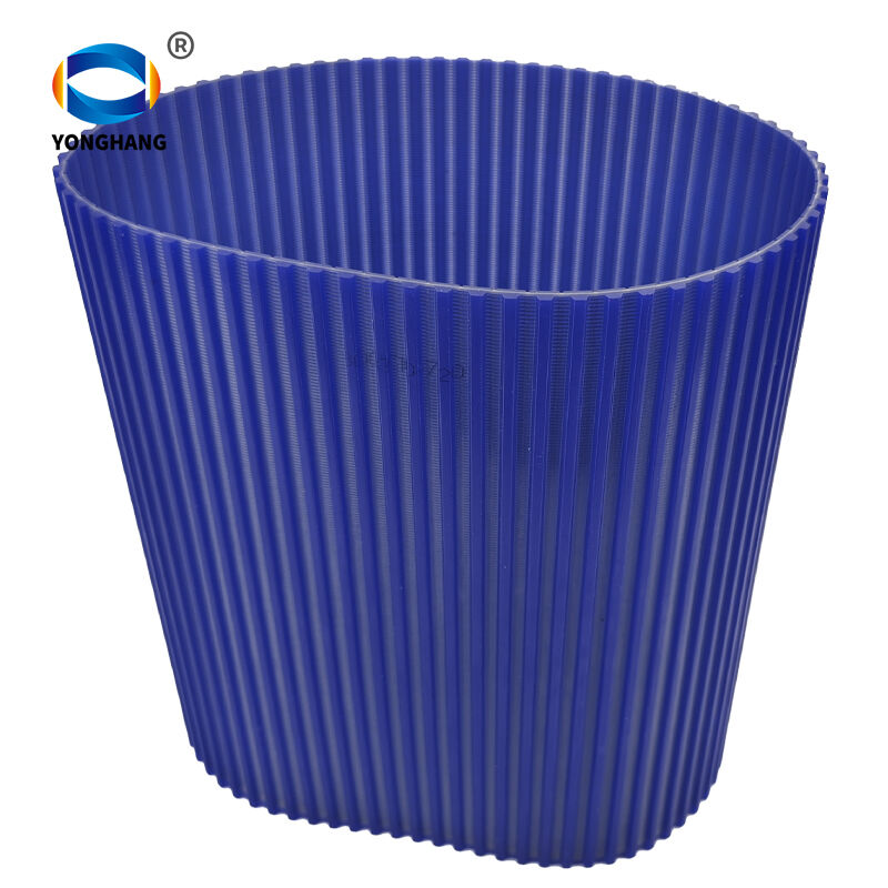
What exactly is a back groove? It refers to a calculated series of fine longitudinal channels or serrations precision-engineered along the entire length of the timing belt's posterior surface (the flat side, opposite the teeth).
Far from being mere aesthetic choices, these grooves are functional design elements critical to optimizing the belt's interaction with the drive system.
2. The Two Primary Manufacturing Methodologies
The process of creating these grooves is vital to the belt's structural integrity. Depending on production volume and specific application needs, manufacturers utilize two main methods:
I. Integrated, One-Piece Molding (Standard Production)
This is the most widespread approach, where the raised ridges required for the grooves are integrated directly onto the mold rollers.
-
Process: During the initial polyurethane (PU) casting or injection molding phase, the reverse grooves are molded into the belt structure in a single, synchronized step. This eliminates any need for secondary processing.
-
Best For: Seamless, full-circumference timing belts and high-volume production runs.
-
Characteristics: Ensures a standardized groove profile. Crucially, because it is molded, it does not damage the internal steel core reinforcement, preventing cuts, stress fractures, or cracks.
II. Secondary, Post-Production Milling (Customization)
For custom requirements or smaller runs, a standard flat-backed belt is modified.
-
Process: After the base timing belt is fully manufactured, a computerized numerical control (CNC) machine or specialized grooving equipment is used to mill the channels into the back surface.
-
Best For: Small batches, open-ended belts, non-standard bespoke orders, and the retrofitting of existing inventory.
-
Characteristics: Offers unparalleled flexibility for custom groove configurations. However, precise depth control is critical during milling to ensure the machinery does not cut into and weaken the vital tensile cord core.
3. Practical Operational Benefits of Back Grooves: The Workshop Perspective
Why do experienced plant managers and maintenance engineers specifically request back-grooved belts? The advantages are evident across several performance categories:
Superior Flexibility and Optimized Bending Resistance
The primary functional benefit is a dramatic increase in the belt’s ability to bend. By reducing the thickness of the material that must compress and stretch, the belt handles tight bends with ease. This makes it ideal for use with small-diameter pulleys. Furthermore, it is less susceptible to cracking during high-frequency reverse operation (backbending) or frequent start-stop cycles, thereby significantly extending the operational lifespan of the belt.
Noise Reduction, Vibration Damping, and Reduced Screeching
High-speed belt operation often generates air entrapment between the belt back and the pulley surface. As air is rapidly compressed and expelled, it causes a characteristic screeching or high-pitched sound. Back grooves provide an escape path (ventilation) for this air. Air is expelled smoothly, eliminating compression screech and remarkably reducing overall noise levels.
Superior Heat Dissipation and Enhanced Resistance to Aging
Operation creates friction, which creates heat. If the heat is trapped, it can lead to the PU material softening, subsequent hardening, and premature aging. The reverse grooves effectively increase the belt’s total surface area, functioning as miniature cooling fins. This facilitates faster heat dissipation and maintains the optimal operating temperature of the PU material.
Efficient Debris Management and Contaminant Expulsion
In industrial environments, dust, oil, and debris are constant challenges. These contaminants can get trapped between the pulley and the belt, leading to slippage and accelerated wear. Back grooves act as channels, carrying debris and oil away from the critical contact surfaces and preventing contamination buildup.
Internal Stress Elimination and Deformation Resistance
The process of PU molding often introduces subtle internal tensions. Grooving helps release these internal stresses within the belt body. A belt with released stress is less prone to unwanted twisting, stretching, or misalignment, resulting in more stable and reliable power transmission.
Enhanced Stability for High-Speed and Precision Applications
By offering improved flexibility and debris removal, back grooves reduce operational vibration and resonance. This increased stability makes them indispensable for precision conveying and high-speed automated transmission equipment where tracking accuracy is paramount.
Conclusion
Whether molded for high-volume efficiency or CNC-milled for bespoke customization, the PU timing belt back groove is a small detail that delivers large-scale results. By optimizing flexibility, reducing noise, managing heat and contamination, and enhancing structural stability, these grooves ensure that timing belts deliver their promised efficiency even under the most demanding workshop conditions.
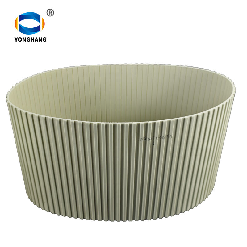
Table of Contents
- 1. Defining the PU Timing Belt Back Groove
- 2. The Two Primary Manufacturing Methodologies
-
3. Practical Operational Benefits of Back Grooves: The Workshop Perspective
- Superior Flexibility and Optimized Bending Resistance
- Noise Reduction, Vibration Damping, and Reduced Screeching
- Superior Heat Dissipation and Enhanced Resistance to Aging
- Efficient Debris Management and Contaminant Expulsion
- Internal Stress Elimination and Deformation Resistance
- Enhanced Stability for High-Speed and Precision Applications
- Conclusion