 EN
EN
 AR
AR
 HR
HR
 DA
DA
 NL
NL
 FR
FR
 DE
DE
 EL
EL
 HI
HI
 IT
IT
 JA
JA
 KO
KO
 NO
NO
 PL
PL
 PT
PT
 RO
RO
 RU
RU
 ES
ES
 TL
TL
 IW
IW
 ID
ID
 SR
SR
 SK
SK
 UK
UK
 VI
VI
 TH
TH
 TR
TR
 AF
AF
 MS
MS
 IS
IS
 HY
HY
 AZ
AZ
 KA
KA
 BN
BN
 LA
LA
 MR
MR
 MY
MY
 KK
KK
 UZ
UZ
 KY
KY
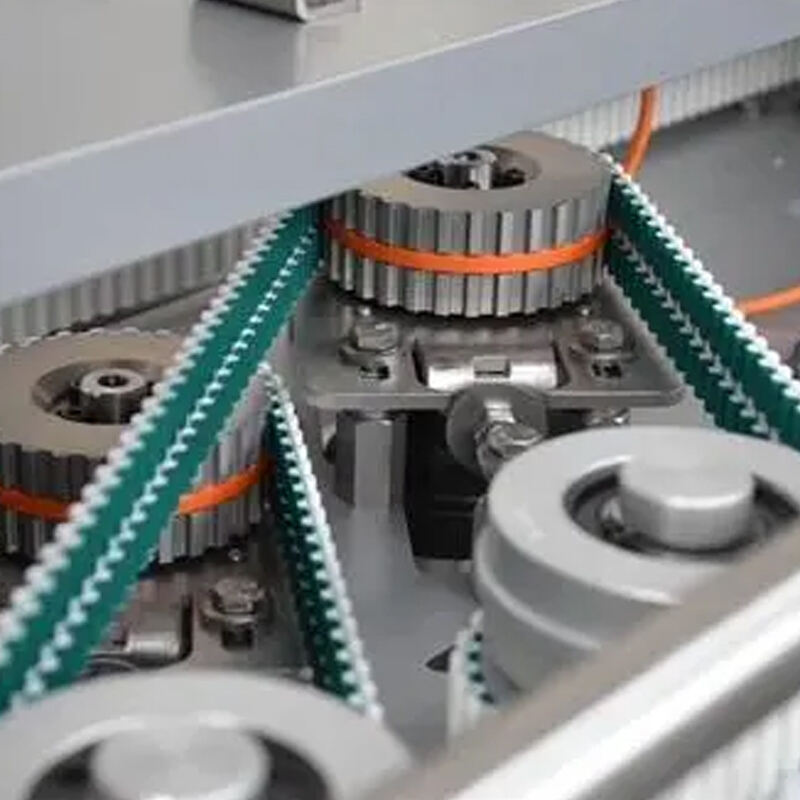
Understanding Timing Pulley and Belt Pitch Compatibility
The importance of matching timing pulley and belt pitch
Getting the right match between timing pulleys and belt pitch matters a lot when it comes to transferring power efficiently. Even a tiny mismatch of just 0.1 mm can slash load capacity by around 30% according to recent findings from Industrial Drive Systems in their 2023 report. That kind of discrepancy often leads to parts wearing out faster or complete system breakdowns down the line. When everything lines up properly though, the shafts move together smoothly without slipping. This synchronization becomes absolutely critical in high precision work environments such as CNC machines and robotic assembly lines where slight variations in movement translate directly into defective products on the production floor.
How tooth engagement ensures precise motion transmission
Getting good motion control really comes down to how well those belt teeth engage with the pulley. When each tooth sits properly in its groove, it spreads out the mechanical stress much better across the system. This matters a lot for setups running at speeds over 5,000 RPM where even small issues can cause big problems. Studies from mechanical engineers show that proper engagement brings backlash down below 0.5 arc-minutes, which makes all the difference for precision work like laser cutting operations and 3D printing applications where accuracy is everything.
Common pitch standards: MXL, XL, L, T5, HTD, and cross-compatibility considerations
The most widely used pitch standards are:
| Pitch | Tooth Profile | Common Applications | Max Speed |
|---|---|---|---|
| MXL | Trapezoidal | Small robotics, printers | 1,500 RPM |
| HTD | Curved | Industrial automation | 6,000 RPM |
Cross-use between profiles such as HTD and STD is generally not recommended due to differences in pressure angles. While some modified designs allow limited interchangeability in low-torque setups, consistent performance requires matched components.
Selecting the right pitch based on application speed and load
When it comes to servo driven systems that need to accelerate quickly, going with smaller belt pitches between 2 and 5 mm like L or XL types really helps cut down on inertia problems. On the flip side, those big industrial conveyor setups usually rely on HTD or T5 belts instead, which have larger pitches ranging from around 8 up to 14 mm. Recent research into powertrains back in 2024 showed something interesting too. The study indicated that when manufacturers take time to pick the right belt pitch for their specific needs, they can actually boost energy efficiency anywhere from 12% all the way up to nearly 18% in cars versus just using whatever standard setup happens to be available off the shelf.
Determining Correct Belt Length and Center Distance
Calculating belt length based on center distance and pitch diameter
Accurate belt length calculation is fundamental to reliable timing drive performance. The standard formula combines center distance (C) and pulley pitch diameters (D1, D2):
| Variable | Description | Formula Component |
|---|---|---|
| L | Belt length | 2C + π(D1 + D2)/2 + (D1 - D2)²/(4C) |
| C | Shaft center distance | Measured between pulley centers |
| D1/D2 | Pitch diameters | Tooth count × pitch |
This method, referenced in mechanical power transmission guidelines, ensures 85–90% of belt teeth remain engaged under load for optimal stress distribution.
Standard formulas for fixed-center and adjustable pulley setups
Fixed-center systems require belt lengths within ±0.2% of the calculated value. For adjustable setups, a 1–3% variance is acceptable while maintaining operational integrity. Design constraints include:
- Minimum center distance = (D1 + D2)/2 + 15% of belt width
- Maximum center distance = 3 × (D1 + D2)/2
These ranges support proper tensioning without overloading components.
Adjusting center distance for proper tension and alignment
Fine-tuning center distance by 0.5–2 mm after installation achieves optimal belt tension. Critical alignment parameters include:
- Parallelism error < 0.5° between shafts
- Radial runout < 0.1 mm
- Axial misalignment < 1% of belt width
Proper alignment minimizes edge loading and extends service life.
Impact of incorrect belt length on system efficiency and wear
Belts that are too long reduce tooth engagement by 18–22%, while undersized belts increase shear stress on teeth by 35–40%. Both conditions result in:
- 25–30% loss in power transmission efficiency
- Twice the wear rate in high-torque environments
- Premature bearing failure in pulleys
Precision in length selection directly affects reliability and maintenance intervals.
Selecting the Right Timing Belt Width and Load Capacity
Matching Belt Width to Torque and Load Requirements
Belt width must align with peak torque and radial load demands. Undersized belts stretch prematurely; oversized versions add unnecessary inertia and space requirements. For example, industrial CNC machines operating at 80–120 N·m typically use belts between 25–50 mm wide to maintain accuracy under dynamic loads.
How Wider Belts Improve Durability in High-Torque Applications
Wider belts, around 25 mm and above, distribute mechanical stress over more teeth which cuts down on the shear force each tooth experiences. Tests show this can reduce those forces by somewhere between 18 to 22 percent when compared with narrower belt options. For applications like robotic arms or heavy duty conveyor systems where sudden torque jumps often go past what's normal by about 150%, these wider belts perform much better. When looking at materials, polyurethane belts that have steel reinforcement cords inside actually handle about 25 to 40 percent more weight than regular rubber belts do in similar tough situations. Many manufacturers have found this difference makes a real impact in their operations.
Narrow vs. Wide Belts: Performance Trade-Offs in Industrial Settings
- Narrow belts (≤15 mm): Ideal for compact, high-speed systems (<3,000 RPM) but limited to loads under 50 N·m
- Wide belts (25–100 mm): Used in presses, extruders, and mining equipment transmitting 100–1,000 N·m
- Hybrid designs (15–25 mm): Balance moderate torque (50–200 N·m) and speed requirements
Selection should reflect space, inertia, and duty cycle constraints.
Material and Reinforcement Factors in Timing Belt Selection
Material choice significantly influences durability and load handling. Key pairings include:
| Application Type | Ideal Material | Max Load Capacity |
|---|---|---|
| High-torque industrial | Polyurethane + Kevlar | 1,200 N·m |
| Food processing | Oil-resistant rubber | 450 N·m |
| Precision automation | Neoprene + fiberglass | 320 N·m |
| High-temperature | Thermoplastic elastomer | 680 N·m |
In chemically aggressive environments, polyurethane belts with stainless steel tensile cords provide three times greater acid resistance than nitrile-based alternatives. Always confirm pulley groove geometry matches the belt profile to avoid misalignments of 0.05–0.2 mm that accelerate wear.
Proper Installation and Maintenance of Timing Pulley Systems
Best practices for installing timing belts and pulleys
Installation quality determines nearly 90% of a belt’s service life, according to power transmission studies. Essential steps include:
- Clean pulley grooves before assembly
- Verify alignment using laser tools or straightedges
- Apply even axial pressure when seating the belt—never use levers
- Rotate the system manually through three full revolutions post-installation
Following these procedures prevents initial damage and promotes uniform load sharing.
Ensuring pulley alignment for maximum efficiency and lifespan
Shaft misalignment beyond 0.5° shortens belt life by 47% in industrial settings. Use dial indicators to measure:
- Parallelism between shaft centerlines
- Angular alignment of pulley faces
- Vertical and horizontal offset across rotation
Even slight misalignments cause uneven tooth wear and increased noise.
Tension adjustment techniques to reduce noise and wear
Optimal tension corresponds to a deflection of 1/64" per inch of span length. Accurate measurement methods include:
- Frequency meters to detect natural vibration frequency
- Force deflection gauges compliant with ISO 4184
- Automated tensioning systems in precision-critical applications
Consistent tensioning reduces slippage, heat buildup, and noise.
Routine maintenance tips to prevent premature failure
Monthly inspections reduce unplanned downtime by 81% (2023 condition monitoring study). Recommended practices:
- Record tooth wear patterns every 500 operating hours
- Monitor pulley groove width expansion (replace if >3% wider than original)
- Prevent contamination using V-ring seals
- Lubricate bearings carefully to avoid oil migration onto belts
Replace belts at 90% of their rated service life in critical systems, and always replace pulleys and belts as a matched set to ensure compatibility and performance consistency.
FAQ
Why is the alignment of timing pulleys and belts so important?
Proper alignment is crucial because misalignment can lead to uneven tooth wear, increased noise, and significantly reduced lifespan of the belt, potentially affecting system efficiency and performance.
How often should timing belt systems be inspected?
It's recommended to conduct inspections monthly, as consistent monitoring can reduce unplanned downtime significantly.
What factors should be considered when selecting a timing belt material?
Key factors include the application's torque requirements, environmental conditions (such as exposure to chemicals), and temperature, as different materials offer varying levels of durability and resistance to environmental factors.
Can different pitch profiles be interchanged for low-torque applications?
While it is possible, consistent performance is only guaranteed with matched components due to differences in pressure angles and tooth profiles.